- 您现在的位置:买卖IC网 > Sheet目录323 > DV164039 (Microchip Technology)KIT DEV PIC24FJ256DA210
�� �
�
�PIC24FJ256DA210� Development� Board� User’s� Guide�
�4.4.4.3�
�RESISTIVE� TOUCH� SCREEN� INTERFACE�
�The� development� board� supports� display� panels� with� a� built-in� 4-wire� resistive� touch�
�screen.� The� resistive� touch� screen� interface� (X-,� Y-,� X+� and� Y+)� is� used� to� directly� con-�
�nect� to� the� touch� screen� signals.� X+� and� Y+� are� both� analog� and� digital� signals,� and�
�are� connected� to� I/O� ports� that� can� function� both� as� analog� inputs� and� digital� outputs.�
�X-� and� Y-� are� digital� output� signals� only,� and� are� connected� to� digital� I/O� ports.� The� X+�
�and� Y-� signals� are� multiplexed� with� the� SPI� based� touch� screen� controller.�
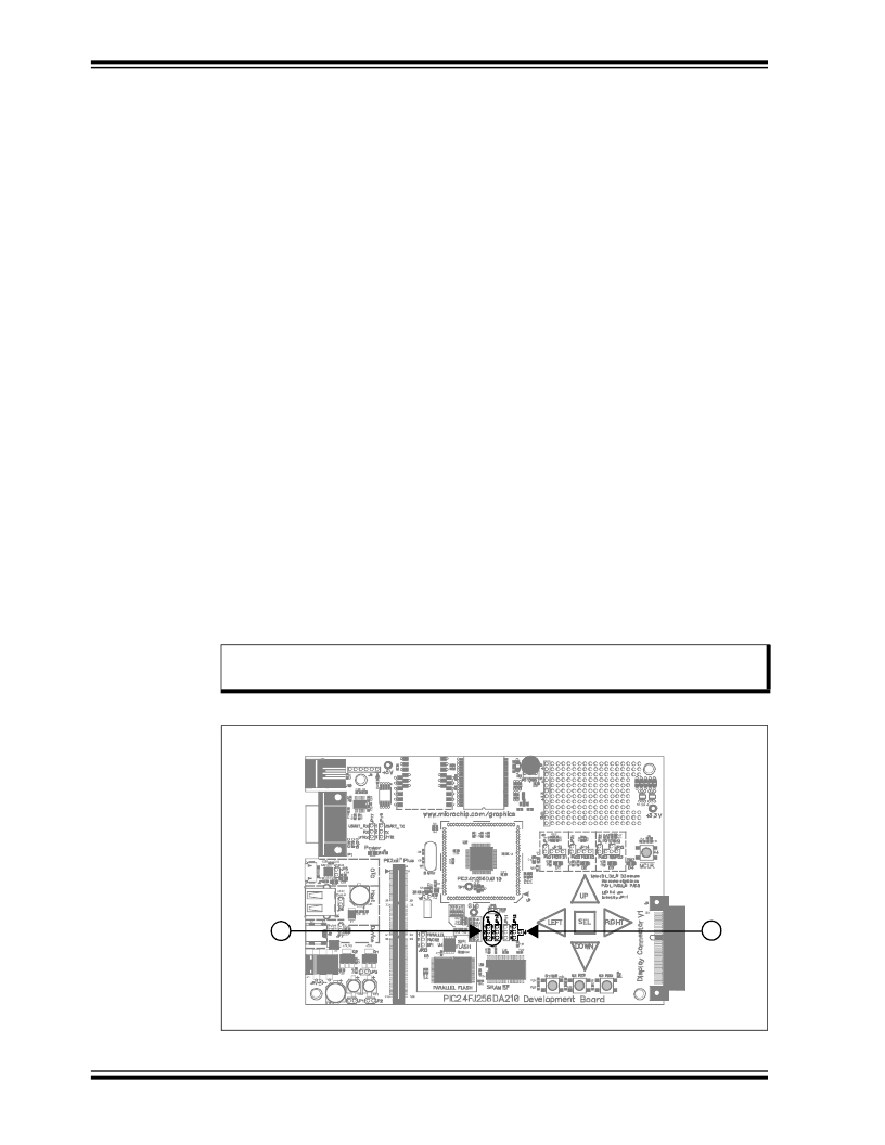
�When� using� the� 4-wire� resistive� touch� screen� interface,� jumpers� JP9� and� JP10� must� be�
�set� to� their� default� positions,� bridging� pins� 1� and� 2� (Figure� 4-7,� callout� 1).�
�4.4.4.4�
�SPI� TOUCH� CONTROLLER� INTERFACE�
�Two� SPI� channels� (two� Chip� Select� lines)� are� provided� in� Display� Connector� V1� to�
�support� display� panels� equipped� with� the� following:�
�?� SPI-Based� Timing� Controller:� Some� displays� requires� programming� of� an�
�on-board� Timing� Controller� (TCON)� to� initialize� the� settings� of� the� display� before� it�
�is� used.� The� TCON� is� used� to� synchronize� the� display� glass� timing� with� the� dis-�
�play� controller� signal� timing.� This� option� is� provided� on� the� pins� A27� (SPI_SCK),�
�A28� (SPI_MISO),� B27� (DISP_SPI_CS)� and� B28� (SPI_MOSI)� of� display� connector�
�V1.�
�?� SPI-Based� Touch� Controller:� In� some� cases,� an� SPI-based� touch� module� is� used�
�with� the� display.� Every� time� a� touch� is� detected,� it� sends� an� interrupt� to� the� host�
�controller� to� inform� the� host� that� there� is� a� fresh� touch� input� and� the� information�
�must� be� forwarded� from� the� touch� module� to� the� host� controller� through� SPI� com-�
�munications.� The� development� board� shares� two� of� the� pins� of� the� 4-wire� resistive�
�touch� screen� with� the� interrupt� and� chip� select� line� of� the� SPI� based� touch� control-�
�ler.� The� sharing� is� done� this� way� since� in� any� system,� only� one� of� the� two� types� of�
�user� interface� will� be� used.�
�The� SPI-based� touch� control� features� are� configured� by� jumpers� JP9� and� JP10�
�(Figure� 4-7,� callout� 1).� To� enable� the� use� of� an� SPI-based� touch� controller,� set� jumpers�
�JP9� and� JP10� to� bridge� positions� 2-3.�
�Note:�
�As� of� this� writing,� none� of� the� Microchip� display� boards� support� SPI-based�
�touch� controllers.�
�DS51911A-page� 42�
�FIGURE� 4-7:�
�1�
�TOUCH� CONTROLLER� AND� BACKLIGHT� CONFIGURATION�
�2�
�M�
�?� 2010� Microchip� Technology� Inc.�
�发布紧急采购,3分钟左右您将得到回复。
相关PDF资料
DV164101
KIT DEV PICKIT1 FLASH 8/14PIN
DV164120
KIT STARTER PICKIT 2
DV164121
KIT PICKIT 2 DEBUG EXPRESS
DV164122
ANALYZER SRL PICKIT W/DEMO BOARD
DV164131
KIT STARTER PICKIT 3
DV164132
KIT EVAL F1 FOR PIC12F1/PIC16F1
DV243003
KIT STARTER FOR SRL MEM PRODUCTS
DVA1001
ADAPTER FOR PIC16F716 18DIP
相关代理商/技术参数
DV164101
功能描述:开发板和工具包 - PIC / DSPIC PICkit 1 8/14P Flash RoHS:否 制造商:Microchip Technology 产品:Starter Kits 工具用于评估:chipKIT 核心:Uno32 接口类型: 工作电源电压:
DV164101
制造商:Microchip Technology Inc 功能描述:TOOLS: FLASH MICROCONTROLLER (
DV164102
功能描述:开发板和工具包 - 无线 rfPICkit RoHS:否 制造商:Arduino 产品:Evaluation Boards 工具用于评估:AT32UC3L 核心:AVR32 频率: 接口类型:USB 工作电源电压:5 V
DV164120
功能描述:电路内置调试器 PICkit 2 8/14/20P Flash RoHS:否 制造商:Microchip Technology 产品:In-Circuit Debugger Kits 工具用于评估:PIC MCUs, dsPIC DSCs 用于:07-00024, AC164113 核心:dsPIC, PIC 接口类型:USB 工作电源电压:3 V to 5 V
DV164121
功能描述:电路内置调试器 PICkit 2 Debug Express RoHS:否 制造商:Microchip Technology 产品:In-Circuit Debugger Kits 工具用于评估:PIC MCUs, dsPIC DSCs 用于:07-00024, AC164113 核心:dsPIC, PIC 接口类型:USB 工作电源电压:3 V to 5 V
DV164121
制造商:Microchip Technology Inc 功能描述:ICPICKIT2 PROGRAMMER/DEBUGGER ((NW))
DV164121+TEFLCST3
制造商:Microchip Technology Inc 功能描述:KIT PICKIT2+FLOWCODE-HOME BUNDLE 制造商:Microchip Technology Inc 功能描述:ICD, PICKIT 2, FLOW CODE, PIC, DSPIC 制造商:Microchip Technology Inc 功能描述:ICD, PICKIT 2, DEBUG EXP, FLOW CODE, PIC, DSPIC; Silicon Family Name:PIC12F6xx, PIC16F5xx; Core Architecture:PIC; Core Sub-Architecture:PIC12, PIC18, PIC24; IC Product Type:Debugger / Programmer; Series:PICkit 2 ;RoHS Compliant: Yes
DV164122
功能描述:界面开发工具 PICkit Ser Analyzer RoHS:否 制造商:Bourns 产品:Evaluation Boards 类型:RS-485 工具用于评估:ADM3485E 接口类型:RS-485 工作电源电压:3.3 V